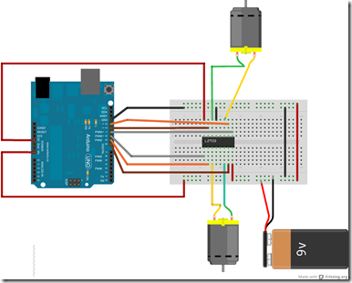
http://hardwarefun.com/tutorials/creating-robots-using-arduino-h-bridge
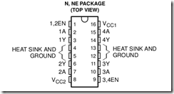
The following is the explanation for the different pins of the IC.
Vcc1 (pin 16) takes in regulated 5V for operating the IC.
Vcc2 (pin 8) takes the external voltage (up to 36V) which
1,2 EN (pin 1) and 3,4 EN (pin 9) are the enable pins for the two motors
1A (pin 2) and 2A (pin 7) are the control pins for Motor 1. These will be connected to Arduino.
1Y (pin 3) and 2Y (pin 6) are the output pins for Motor 1. These will be connected to the first motor.
3A (pin 10) and 4A (pin 15) are the control pins for Motor 2. These will be connected to Arduino.
3Y (pin 11) and 4Y (pin 14) are the output pins for Motor 2. These will be connected to the second motor.
pins 4,5,12,13 are Gnd pins


